|
情報科学センター年報,第32号,2004年3月より |
FPGAにおけるRS232C通信の実現
A RS232C SERIAL INTERFACE IP-CORE FOR THE FPGA
舞鶴工業高等専門学校 電子制御工学科
町田秀和(machida@maizuru-ct.ac.jp)
1.はじめに
現在,電子制御機器の中核となるマイクロコンピュータは,PIC等の大変高速かつ
1チップに数多くの機能を内蔵した多くの品種が利用でき,ロボットコンテストでも
数多く使われている.また,FPGA(Field Programmable Gate Array:現場で回路を
書き込めるIC)も最近の微細加工技術の進歩によりますます高速大容量化が進んでおり,
SOPC(System on a programmable chip:1チップに種々の回路を組み込んでシステムを
実現する)が実用段階に入っている.
本稿では,SOPCを実現する上でFPGAの基本回路モジュール(一般的にはIP(Intellectual
property:知的財産)コアと呼ばれる)として,1チップマイコンやパソコンなどと
データ通信を行う目的で,もっとも基本的なシリアル通信手段であるRS232C通信の
ための回路の実現例を紹介する.
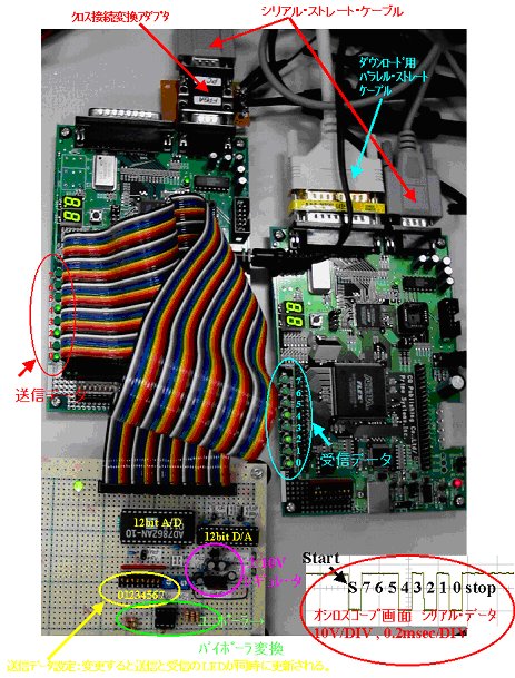
図9.FPGA評価ボード間のRS232C通信実験状況
2.RS232Cシリアル通信とFPGA
RS232Cシリアル通信 は,1969 年に米国の EIA(アメリカ電子工業会)が CCITT
(国際電信電話諮問委員会)勧告に基づき データ端末と回路終端装置とのインター
フェース条件を 決めた歴史のある標準化された規格でパソコン周辺機器をはじめ
,様々な装置の入出力インターフェースとして幅広く使用されている.特にFA関連分野
ではパソコン,モデム,バーコードリーダ,PLCなどの標準的なインターフェース
として使われている.
最近では,パソコン用のUSBや,デジタルビデオ用のIEEE1394などの,パケット通信
に基づく高速な規格が注目を集めているが,RS232Cは大変原始的なシルアル通信規格
であり,ハードウェアおよびソフトウェア両面で簡単かつ安価に実現できるため,
まだまだ利用されつづけるであろう.例えば,数百円の1チップマイコンPICにも
RS232Cのハードウェア回路が内蔵されておりPIC間あるいは,PICとパソコンの間
のデータ通信手段として用いられている.
一方で,FPGAは基本的にユーザが回路を全て設計しなければならないが,FPGA
ベンダーあるいはインターネットで公開されているRS232C通信のIPコアは意外と
少なく,また高度な通信手順を実現するために複雑になっている.ここでは,
最も基本的でパソコンの通信ターミナルソフトなどでのデフォルトの手順である,
非同期(調歩同期式),パリティなし,ストップビット1のRS232C通信用IPコアを設計する.
なお,RS232Cの電気的規格によると,電源電圧は±15V,伝送速度は20kbit/sec以下,
距離は15m以下とされている.このため図1に示すように,パソコン(±12V)と,
PICやFPGAの電源電圧(5V)と電圧レベルを適合させるため,DC-DCコンバータを
備えた専用の電圧レベル変換IC(MAX232シリーズが有名)が用いられる.しかしながら,
PICやFPGAどおしを近距離で直接通信するためには,この電圧レベル変換ICは不要であるし,
実装に気をつければかなり高速の通信も実現することができる.
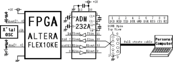
図1.FPGAとパソコン間のRS232C通信
3.送信回路
送信回路は図2のブロック図に示すように,
- パラレルデータ入力からシリアルデータを生成し出力する送信モジュールRS232CS
- 送信モジュールを起動し,送信終了まで待機する送信ドライバSENDER
で構成する.図2にはこれらをテストするために,
- クロック発生用リップルカウンタRIP
- 同期化器シンクロナイザSSYNC
を用いている.
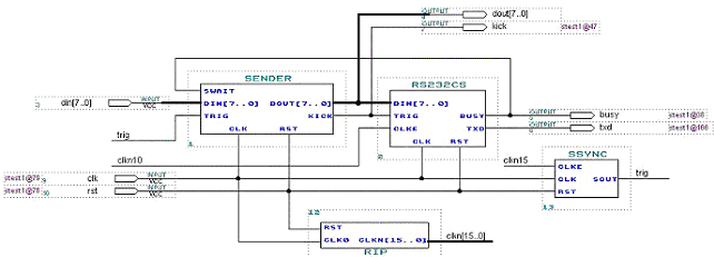
図2.送信回路のブロック図(stest1.gdf)
ここで,シリアル通信のデータ列は図4に示すように,無信号時はハイレベル(以後'1')
で,1ビット幅のローレベル(以後'0')のスタートビットに続いて,8bitの'0'あるいは
'1'のビット列が続き,その後0bit(すなわち省略)のパリティビット(これを加えた
データビット中の'1'の個数が偶数か奇数)の後,1ビット幅の'1'のストップビットが続く.
通信速度は送信側と受信側で一致していることを互いに信頼した非同期である.
8bitの入力データをdin[7..0]に与え,busy端子が'0'であるのを確認してから,
trig端子を同期'1'アサートすると,RS232C非同期(調歩同期式)信号がtxd端子から
出力される.送信中はbusy端子に'1'が出力されている.通信速度はclke端子に
与える周波数で設定する.clkeに与える信号は内部で同期化されるので,外部で
同期化する必要はない.ここでは,20MHzを1/211した約9600bpsであり,また
1/216した約300Hzで連続送信している.
なお,RS232Cレベル・コンバートICが信号を反転するので,txd端子の信号は
反転している.
3.1 送信ドライバ(sender.vhd)
表1に送信ドライバの入出力信号,図3にタイミング波形図と状態遷移図を示す.
表1.送信ドライバの入出力信号
| 端子名 | 方向 | 意味 |
| din[7..0] | in | データ入力 |
| swait | in | 送信完了待ち |
| trig | in | データ入力ラッチ(要同期) |
| dout[7..0] | out | データ出力 |
| kick | out | RS232C送信要求 |
| clk,rst | in | システムクロック・リセット |
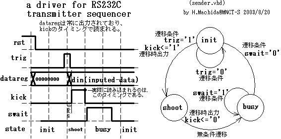
図3.送信ドライバのタイミング波形図と状態遷移図
3.2 送信モジュール(rs232cs.vhd)
表1に送信ドライバの入出力信号,図3にタイミング波形図と状態遷移図を示す.
trig入力でパラレルデータをロードし,clkeのタイミングでシリアルデータを出力する.
表2.送信モジュールの入出力信号
| 端子名 | 方向 | 意味 |
| din[7..0] | in | データ入力 |
| trig | in | 送信開始 '1'同期アサート |
| clke | in | 送信ボーレート内部で同期 |
| txd | out | 反転RS232C出力信号 |
| busy | out | 送信中は'1'になる. |
| clk,rst | in | システムクロック・リセット |
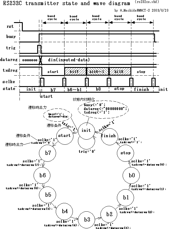
図4.送信モジュールのタイミング波形図と状態遷移図
3.3 シンクロナイザ(ssync.vhd)
表3にシンクロナイザの入出力信号,図5にタイミング波形図と状態遷移図を示す.
表3.シンクロナイザの入出力信号
| 端子名 | 方向 | 意味 |
| clke | in | 非同期クロック入力 |
| sout | in | 同期化クロック出力 |
| clk,rst | in | システムクロック・リセット |
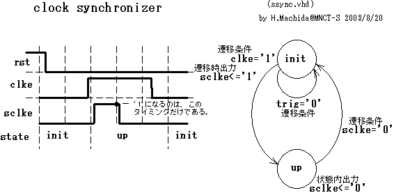
図5.シンクロナイザのタイミング波形図と状態遷移図
4.受信回路
図6にブロック図を示す受信回路は,
- シリアルデータ入力からパラレルデータを生成し出力する受信モジュールRS232CR
と,それをテストするための,
- 同期ラッチTCHK
- (3)クロック発生用リップルカウンタRIP
を用いている.
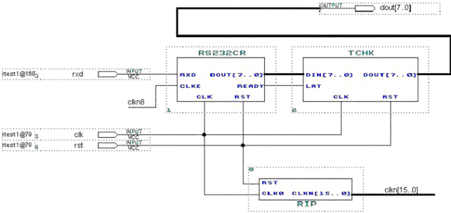
図6.受信回路のブロック図(rtest1.gdf)
RS232C受信入力信号rxdを,8bit並列データに変換しdout[7..0]に出力する.
変換終了はready端子から同期出力されるので,そのタイミングでラッチすればよい.
通信速度はclke端子に与える周波数(ボーレートの4倍)で設定する.clkeに与える
信号は内部で同期化されるので,外部で同期化する必要はない.なお,RS232C
レベル・コンバートICが信号を反転するので,rxd端子の信号は反転している.
4.1 受信モジュール(rs232cr.vhd)
表4に受信モジュールの入出力信号,図7にタイミング波形図と状態遷移図を示す.
シリアルデータ入力nxrdの立ち上がりを検出し,それから2クロック後にまだデータ
が0であれば,4クロック毎にデータを受信していく.ストップビットのタイミング
でラッチフラグreadyを立てる.
表4.受信モジュールの入出力信号
| 端子名 | 方向 | 意味 |
| rxd | out | 反転RS232C入力信号 |
| clke | in | 受信ボーレートの4倍 |
| dout[7..0] | out | 出力8bitデータ |
| ready | out | 受信完了同期出力 |
| clk,rst | in | システムクロック・リセット |
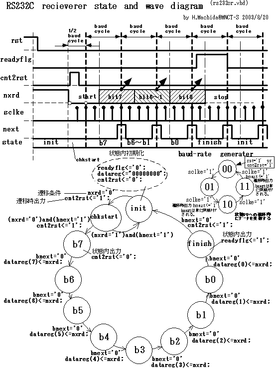
図7.受信モジュールのタイミング波形図と状態遷移図
4.2 同期ラッチ(tchk.vhd)
表5に同期ラッチの入出力信号,図8にタイミング波形図と状態遷移図を示す.
表5.同期ラッチの入出力信号
| 端子名 | 方向 | 意味 |
| din[7..0] | in | 入力データ |
| lat | in | ラッチ要求入力 |
| dout[7..0] | out | 出力データ |
| clk,rst | in | システムクロック・リセット |
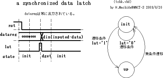
図8.同期ラッチのタイミング波形図と状態遷移図
5.FPGA実現
全ての回路はALTERA社の統合EDAツールMAX+PLUS2上でVHDL言語で記述し
シミュレーションで動作確認した.全てのVHDLソースリストを付録に示す.
そして図9に示すようにCQ出版社のALTERA FLEX10KE FPGA評価ボード2台間で通信
実験を行った.パソコンのパラレルポート経由で回路をダウンロードし,
FPGA評価ボードどおしはクロス接続アダプタを介してD-SUB9pinストレート
ケーブルで接続した.数万bps以上の高速でも通信可能であることが確認できた.
また三菱電機マイコン機器ソフトウェア社のFPGA評価ボードMU200-EA10
(FPGAはALTERA FLEX10K10)とパソコン(WindowsのHyper Terminal)間で通信速度
は若干異なる(FPGA:20MHz/216=9766bps,PC:9600bps,約1.7%差)条件で通信実験
したが問題なく正確な通信が実現できた.

図9.FPGA評価ボード間のRS232C通信実験状況
6.おわりに
FPGA用の非同期RS232C通信IPコアを開発した.USBであればプロトコル
アナライザ等が必要であるが,RS232Cは原始的なシリアル通信規格である
のでディジタルオシロスコープで通信状況を確認できるので実験は容易で
あった.シリアル通信であるので,わずか2,3本の銅線で瞬時に通信が行える
のは,やはり大変便利である.今後は,ホストの1チップマイコンPIC等と
通信して,FPGAのSOPCのパラメータを設定するためのシーケンサなどを
開発していく予定である.なお,本IPコアはホームページ上でフリーIP
コアとして公開する予定である.
謝辞
本研究では,ALTERA社のUniversity Program制度で無償提供された
統合EDAツールMAX+PLUS2を用いている.現在まで一番使い勝手が良く
高速だったのはMAX+PLUS2であった.ここに感謝の意を表す.
# 最新のQuartusII Ver.3.0 も評価中である。最新のFPGA ALTERA Cyclone
# にも本RS232Cコア等を実装して評価中である。
参考文献
- トランジスタ技術Special No.8:特集データ通信技術の全て,CQ出版社
- トランジスタ技術Special No9:特集パソコン周辺機器インターフェース紹介,CQ出版社
付録:VHDLソースリスト
list1 送信モジュール(rs232cs.vhd)
--------------------------------------------------------
-- asynchronous rs232c sender circuit
--  written by H.Machida@MNCT-S  2003/8/12
--------------------------------------------------------
library ieee;
use ieee.std_logic_1164.all;

entity rs232cs is port
(  trig  : in std_logic;      -- sending sequence start trigger
   din   : in  std_logic_vector(7 downto 0); -- input data
   clke  : in  std_logic;     -- a frequency equal to baud rate
   txd   : out std_logic;     -- output serial data signal
   busy  : out std_logic;     -- this sequencer is in busy flag
   clk,rst : in  std_logic ); -- system clock and reset
end;
architecture rtl of rs232cs is
  type clkesync_states is (init,up);
  signal clkesync_current : clkesync_states;
  signal sclke : std_logic; -- synchronized clock enable
  type rs232cs_states is (init,start,b7,b6,b5,b4,b3,b2,b1,b0,stop,finish);
  signal rs232cs_current : rs232cs_states;
  signal txdreg  : std_logic;
  signal datareg : std_logic_vector(7 downto 0);

begin
-- clock enable synchronizer
  process(clk) begin
   if(clk = '1' and clk'event) then if(rst='1') then  sclke <= '0'; clkesync_current <= init;
      else
        case clkesync_current is
          when init =>  if (clke = '1') then  sclke<='1'; clkesync_current <= up; else  clkesync_current <= init;  end if;
          when up =>  sclke<='0';  if (clke = '0') then  clkesync_current <= init;  else  clkesync_current <= up;  end if;
        end case;
      end if;
   end if;
  end process;

-- rs232c sending process
  txd <= not txdreg;
  process (clk)
  begin
     if (clk'event and clk = '1') then if (rst = '1') then txdreg<='1'; busy<='0'; datareg<="00000000"; rs232cs_current <= init;
      else
        case rs232cs_current is
          when init =>  txdreg<='1'; busy<='0'; datareg<="00000000";
            if (trig = '1') then busy<='1'; datareg<=din; rs232cs_current <= start; else rs232cs_current <= init;  end if;
          when start => if (sclke = '1') then txdreg<='0';     rs232cs_current <= b7; else rs232cs_current <= start; end if;
          when b7 => if (sclke = '1') then txdreg<=datareg(7); rs232cs_current <= b6; else rs232cs_current <= b7; end if;
          when b6 => if (sclke = '1') then txdreg<=datareg(6); rs232cs_current <= b5; else rs232cs_current <= b6; end if;
          when b5 => if (sclke = '1') then txdreg<=datareg(5); rs232cs_current <= b4; else rs232cs_current <= b5; end if;
          when b4 => if (sclke = '1') then txdreg<=datareg(4); rs232cs_current <= b3; else rs232cs_current <= b4; end if;
          when b3 => if (sclke = '1') then txdreg<=datareg(3); rs232cs_current <= b2; else rs232cs_current <= b3; end if;
          when b2 => if (sclke = '1') then txdreg<=datareg(2); rs232cs_current <= b1; else rs232cs_current <= b2; end if;
          when b1 => if (sclke = '1') then txdreg<=datareg(1); rs232cs_current <= b0; else rs232cs_current <= b1; end if;
          when b0 => if (sclke = '1') then txdreg<=datareg(0); rs232cs_current <= stop; else rs232cs_current <= b0; end if;
          when stop => if (sclke = '1') then txdreg<='1';      rs232cs_current <= finish; else rs232cs_current <= stop; end if;
          when finish => if (sclke = '1') then rs232cs_current <= init; else rs232cs_current <= finish; end if;
        end case;
      end if;
    end if;
  end process;
end rtl;
list2 送信ドライバ(sender.vhd)
----------------------------------------------------
--  RS232C Sender driver for rs232cs.vhd
--      VHDL code written by H.Machida  2003/8/12
------------------------------------------------------
library ieee;
use ieee.std_logic_1164.all;

entity sender is
  port ( din  : in  std_logic_vector(7 downto 0);
         trig,swait,clk,rst : in  std_logic;
         dout : out std_logic_vector(7 downto 0);
         kick : out std_logic );
end sender;

architecture rtl of sender is
  type sender_states is (init,shoot,busy);
  signal sender_current : sender_states;
  signal datareg : std_logic_vector(7 downto 0);
begin
  process (clk)
  begin
     if (clk'event and clk = '1') then  if (rst = '1') then kick<='0'; datareg <= "00000000"; sender_current <= init;
      else
        case sender_current is
          when init =>  kick<='0';
            if(trig='1') then datareg<=din; kick<='1';  sender_current <= shoot; else sender_current <= init;  end if;
          when shoot => kick<='0';  sender_current <= busy;
          when busy =>  kick<='0';  if(swait='1') then  sender_current <= busy; else sender_current <= init; end if;
        end case;
      end if;
    end if;
  end process;
  dout<=datareg;
end rtl;
list3 クロック・シンクロナイザ(ssync.vhd)
--------------------------------------------------------
-- clock synchronizer
--  written by H.Machida@MNCT-S  2003/8/12
--------------------------------------------------------
library ieee;
use ieee.std_logic_1164.all;

entity ssync is port
(  clke  : in std_logic;      -- clock enable signal
   sout  : out std_logic;     -- synchronized clock enable
   clk,rst : in  std_logic ); -- system clock and reset
end;

architecture rtl of ssync is
  type clkesync_states is (init,up);
  signal clkesync_current : clkesync_states;
  signal sclke : std_logic; -- synchronized clock enable
begin
-- clock enable synchronizer
  sout <= sclke;
  process(clk) begin
   if(clk = '1' and clk'event) then if(rst='1') then sclke <= '0';  clkesync_current <= init;
      else
        case clkesync_current is
          when init =>  if (clke = '1') then  sclke<='1'; clkesync_current <= up;  else  clkesync_current <= init;  end if;
          when up =>  sclke<='0'; if (clke = '0') then  clkesync_current <= init;  else  clkesync_current <= up;  end if;
        end case;
      end if;
   end if;
  end process;
end rtl;
list4 受信モジュール(rs232cr.vhd)
--------------------------------------------------------
-- asynchronous rs232c receiver circuit
--  written by H.Machida@MNCT-S  2003/8/12
--------------------------------------------------------
library ieee;
use ieee.std_logic_1164.all;
use IEEE.STD_LOGIC_UNSIGNED.ALL;

entity rs232cr is port
(  clke  : in  std_logic;     -- a frequency x4 to baud rate
   rxd   : in  std_logic;     -- input serial data signal
   dout  : out std_logic_vector(7 downto 0); -- output data
   ready : out std_logic;     -- output vector ready (latch this timing)
   clk,rst : in  std_logic ); -- system clock and reset
end;

architecture rtl of rs232cr is
  type clkesync_states is (init,up);
  signal clkesync_current : clkesync_states;
  signal sclke : std_logic; -- synchronized clock enable
  type rs232cr_states is (init,chkstart,b7,b6,b5,b4,b3,b2,b1,b0,finish);
  signal rs232cr_current : rs232cr_states;
  signal nrxd  : std_logic;  -- inverse rxd data
  signal datareg : std_logic_vector(7 downto 0);
  signal readyflg : std_logic;
  signal cnt2rst : std_logic;
  signal cnt2 : std_logic_vector(1 downto 0);
  signal bnext : std_logic; -- next rxd timing

begin
-- clock enable synchronizer
  process(clk) begin
   if(clk = '1' and clk'event) then if(rst='1') then sclke <= '0'; clkesync_current <= init;
      else
        case clkesync_current is
          when init => if (clke = '1') then sclke<='1'; clkesync_current <= up;  else  clkesync_current <= init;  end if;
          when up =>   sclke<='0';  if (clke = '0') then  clkesync_current <= init;  else  clkesync_current <= up; end if;
        end case;
      end if;
   end if;
  end process;

-- baud rate generater
  process(clk) begin
   if(clk='1' and clk'event) then if(rst='1' or cnt2rst='1') then cnt2<="00"; bnext<='0';
      else
        if(sclke='1' and cnt2(1)='1' and cnt2(0)='1') then cnt2<=cnt2+1; bnext<='1';
        elsif(sclke='1') then cnt2<=cnt2+1;  else bnext<='0'; end if;
      end if;
   end if;
  end process;

-- rs232c sending process
  nrxd<=(not rxd);   dout <= datareg;  ready<=readyflg;
  process (clk)
  begin
     if (clk'event and clk = '1') then
      if (rst = '1') then readyflg<='0'; datareg<="00000000"; cnt2rst<='0'; rs232cr_current <= init;
      else
        case rs232cr_current is
          when init =>  readyflg<='0'; datareg<="00000000"; cnt2rst<='0';
            if (nrxd='0')  then cnt2rst<='1';  rs232cr_current <= chkstart; else rs232cr_current <= init;  end if;
          when chkstart =>   cnt2rst<='0';
            if (nrxd='0' and sclke='1') then  cnt2rst<='1'; rs232cr_current <= b7;
            elsif (nrxd='1' and sclke='1') then  rs232cr_current <= init;
            else  rs232cr_current <= chkstart;  end if;
         when b7 => cnt2rst<='0'; if (bnext='1') then datareg(7)<=nrxd; rs232cr_current <= b6; else rs232cr_current <= b7; end if;
          when b6 => if (bnext='1') then datareg(6)<=nrxd; rs232cr_current <= b5; else rs232cr_current <= b6; end if;
          when b5 => if (bnext='1') then datareg(5)<=nrxd; rs232cr_current <= b4; else rs232cr_current <= b5; end if;
          when b4 => if (bnext='1') then datareg(4)<=nrxd; rs232cr_current <= b3; else rs232cr_current <= b4; end if;
          when b3 => if (bnext='1') then datareg(3)<=nrxd; rs232cr_current <= b2; else rs232cr_current <= b3; end if;
          when b2 => if (bnext='1') then datareg(2)<=nrxd; rs232cr_current <= b1; else rs232cr_current <= b2; end if;
          when b1 => if (bnext='1') then datareg(1)<=nrxd; rs232cr_current <= b0; else rs232cr_current <= b1; end if;
          when b0 => if (bnext='1') then datareg(0)<=nrxd; rs232cr_current <= finish; else rs232cr_current <= b0; end if;
          when finish =>   readyflg<='1';
            if (bnext='1') then rs232cr_current <= init;  else rs232cr_current <= finish; end if;
        end case;
      end if;
    end if;
  end process;
end rtl;
list5 同期ラッチ(tchk.vhd)
----------------------------------------------------
--      VHDL code written by H.Machida
--  data transfer timing checker for recver and sender
------------------------------------------------------
library ieee;
use ieee.std_logic_1164.all;
entity tchk is
  port ( din         : in  std_logic_vector(7 downto 0);
       lat,clk,rst : in  std_logic;
       dout        : out std_logic_vector(7 downto 0) );
end tchk;

architecture rtl of tchk is
  type tchk_states is (init,dget);
  signal tchk_current : tchk_states;
  signal datareg : std_logic_vector(7 downto 0);
begin
  -- Synchronous process
  tchk_init:
  process (clk)
  begin
     if (clk'event and clk = '1') then if (rst = '1') then  datareg <= "00000000";  tchk_current <= init;
      else
        case tchk_current is
          when init =>  if(lat='0') then tchk_current <= init; else tchk_current <= dget; end if;
          when dget => datareg <= din;  tchk_current <= init;
        end case;
      end if;
    end if;
  end process;
  dout<=datareg;
end rtl;
ご意見ご感想はこちらまで!!


