「PLD/FPGAの応用と設計」
舞鶴工業高等専門学校 電子制御工学科 町田秀和
http://sun1.maizuru-ct.ac.jp/control/machida ,
machida@maizuru-ct.ac.jp
1999年7月22日(水) 14:30~京都ポリテクカレッジ、視聴覚教室
ロータリエンコーダ・カウンタを例題として
(1) PLD/FPGAとは何か?
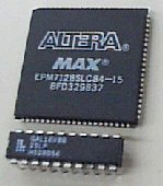
=プログラム可能なIC
← 上は Altera MAX7000
(FPGAあるいは Complex PLDと呼ばれる)
← 下は Lattice GAL16V8(Simple PLDと呼ばれる)
PLD/FPGAのメリット
ユーザ自身がパソコンで回路を設計できる。 |
→ |
技術力の発揮、蓄積の場 |
|---|---|---|
集積化(1チップ化) |
→ |
信頼性の向上 |
内部回路を隠蔽できる |
→ |
技術を盗まれない |
歩留まりが高い |
→ |
冗長回路技術 |
|---|---|---|
不良在庫になりにくい |
→ |
どんな回路にでもできる。 |
結局、安価である |
||
タイムツーマーケット |
: |
他社よりも1日でも早い新製品 |
その他の選択肢との比較
Simple-PLD Lattice GAL16V8の活用例
(2)同期回路設計の考え方
(3)パソコンでのFPGAの開発
ここで紹介するFPGAの開発手順は以下のとおりです。
Visual-HDL for VHDL (SII) のグラフィカル入力例
VHDLとは
ハードウェア記述言語(Hardware
Description Language)の一つ。
その他、ABEL,Verilog-HDL等。
米国防総省が1981年に提唱した
VHS(Very Hige Speed)-IC HDL、
IEEEで標準化されている。
Very Hard
Dificult to Learn と言わ
れているが、それは、回路生成が
不能なコードを書いてしまえるから
で、回路生成が可能な部分だけ
を勉強するなら、難しくはない。
1週間で速習も夢でない。
Architecture RTL of dffe
signal q_in;
begin
  q <= q_in;
  process(ck,d,e,r) begin
    if(ck’event and ck=‘1’) then
      if(r=‘1’) then
        q_in <= ‘0’;
      elsif(e=‘1’) then
        if(d=‘1’) then
          q_in <= ‘1’;
        else
          q_in <=‘0’;
        end if;
     end if;
  end process;
end dffe;
例題:ロータリエンコーダ・カウンタ
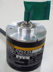
ロータリエンコーダとは、光学式の回転角度センサである。
高精度でノイズに強いがカウント回路が必要。
A相とB相の2つの出力は、互いに
90度
ずれているので、回転方向を弁別できる。
これにより、アップあるいはダウンカウント
すればよい。
また、パルスのカウント法は、右図のよう
に1,2,4逓倍の数え方がある。ここでは、
A相の立ち上りだけの1逓倍でカウントする。
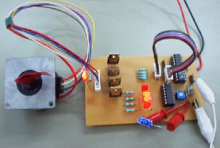
Altera MAX+PLUS2でのFPGA用回路図
(4)PLD/FPGA評価ボードでの実験/検証
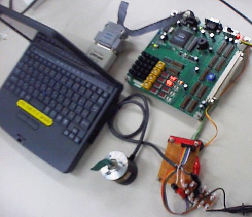
MAX+PLUS2により、上の回路図をコンパイル/フィッティングする。
大変高速(10秒程度)で、スムーズに作業が進む。
パソコンのプリンタポートから
MAX+PLUS2のガードアダプタ
を介して、バイトブラスタ・ケー
ブルで、評価ボードに接続し、
ダウンロードする。
何度でも書きかえられるので、
コストパフォーマンスは高い。
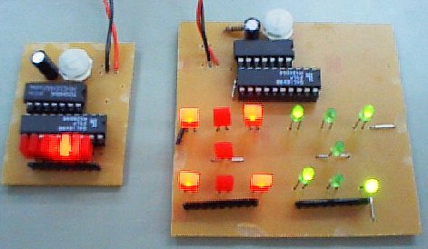
7セグLEDによってカウント値
が、単独LEDによって回転方向
が正しく得られていることを確認。
オシロスコープで波形を確認。
ハードウェア実現なので、超
高速カウントが可能。
(5)まとめと今後の課題
まとめ
今後の課題
付録 FPGAを使い始めるには
必要な開発装置
Visual HDL for VHDL |
|
|---|---|
Accolade PeakVHDL、State CAD |
|
PL-LINK,Synth,Designer |
|
SILOSⅢ(Verilog-HDL) |
|
MAX+PLUS2およびバイトブラスタ・ケーブル |
|
|---|---|
Foundation Tools |
|
PowerMedusa Rapid Proto-typing Kit |
|
|---|---|
マイコンビルダー(パソコンのISA,PCIバス用基板) |
|
VS-SYSTEM & BOARD (プリント基板のみ) |
|
情報
・PLD/FPGAカンファレンス、毎年7月始めごろ東京で
行われる。かなり盛大。この業界の元気なことが良くわかる。
参考文献
Design Wave Magazine |
隔月間 |
\1,990 | |
|---|---|---|---|
小林、三上 |
ABELによるASICの設計技法 |
\3,873 | |
小林 |
ASICのシステム設計 |
\2,500 | |
長谷川 |
VHDLによるハードウェア設計入門 |
\2,345 | |
J.Bhaske |
VHDL言語入門 |
\3,262 | |
奥川 |
LSIによる論理設計 |
\2,781 | |
P.Naish,P.Bishop |
Designing ASIC 同期設計の基本 |
TriEx |
\3,800 |
謝辞
本研究の一部は、以下の補助を受けています。
ほんとうに、どうもありがとうございました!!